


Hydraulic Power Unit Sizing for Dumping Systems
July 11, 2026
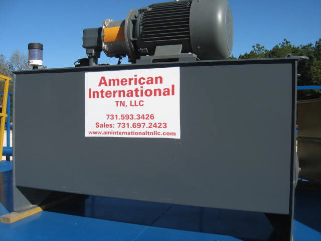
A truck dumper that lifts the rated load but takes too long to cycle is undersized for production. A unit that cycles quickly but overheats after several loads is also undersized, even if its peak pressure looks acceptable on paper. Hydraulic power unit sizing must account for the complete unloading cycle, the actual material load, ambient conditions, machine geometry, and the operating schedule the equipment will face.
For tipping and dumping equipment, the hydraulic power unit is not an accessory. It determines lift performance, controlled lowering, available throughput, component life, and the operator's ability to run the system safely under changing conditions. Proper sizing starts with the machine and the job, not with a catalog horsepower rating.
Start With the Required Force
The first sizing question is how much force the cylinders must develop at each point in the lift. That answer is rarely the same as the gross vehicle weight or container weight. A dumper works through changing leverage as the bed, trailer, or container rotates. The highest cylinder force may occur at breakaway, early in the lift, or at a point where the load's center of gravity moves unfavorably.
Engineering calculations should include the tare weight of the platform or cradle, the maximum loaded vehicle or container weight, and the material's likely distribution. Wet wood residuals, compacted municipal waste, sticky agricultural products, and unevenly loaded scrap can shift differently than free-flowing dry aggregate. A system intended for one predictable load profile can be inefficient or unsafe when assigned a broader mix of materials.
Cylinder bore, rod diameter, mounting geometry, and the number of cylinders establish the available lifting force. The basic relationship is straightforward:
Force = hydraulic pressure × effective piston area
The design work is in determining the pressure required throughout the motion, then providing a realistic margin without routinely driving the system to its relief setting. A relief valve is a protective device, not a normal operating pressure control.
Determine Pressure Before Selecting Horsepower
Once the required cylinder force is known, calculate the working pressure at the most demanding point in the lift. Include pressure losses through directional valves, counterbalance valves, hoses, fittings, filters, manifolds, and any flow-control devices. Long hose runs, restrictive fittings, and undersized return plumbing can create losses that are easy to overlook during preliminary calculations.
A power unit should be designed to operate below the rated pressure of its lowest-rated component. It should also leave enough pressure margin to handle reasonable variation in load condition, hydraulic fluid temperature, and component wear. Excessive margin, however, is not automatically better. Selecting unnecessarily high system pressure can increase cost, complicate component selection, and raise the consequences of leakage or improper service.
For heavy-duty truck dumpers and trailer tippers, pressure requirements must be evaluated alongside structural capacity. Higher cylinder force does not solve a problem caused by inadequate pivot design, poor load restraint, or a machine that is being asked to handle a load outside its intended rating.
Hydraulic Power Unit Sizing Depends on Flow and Cycle Time
Pressure produces force. Flow produces motion. The pump flow rate determines how quickly cylinder volume can be filled and, therefore, how fast the platform rises.
Cylinder extension speed is calculated by dividing pump flow by the total effective cylinder area. The required oil volume is based on cylinder bore area multiplied by the stroke, adjusted for the number of cylinders operating together. From there, the desired lift time determines the necessary flow rate.
For example, a design team may calculate that the lift cylinders require 90 gallons of oil to reach full extension. If the operation needs a 90-second lift, the theoretical pump requirement is 60 gallons per minute. The final selection must account for volumetric efficiency, expected fluid temperature, and any simultaneous hydraulic functions. A nominal 60-GPM pump may not deliver 60 GPM under real operating pressure.
Fast lift speeds improve throughput only when the rest of the process can support them. If the truck must be positioned, restrained, inspected, and cleared before the next vehicle arrives, a faster power unit may provide little operational benefit. Conversely, at a high-volume transfer station or processing plant, a slow lift cycle can become a direct bottleneck.
The right question is not, “How much flow can the pump provide?” It is, “What repeatable cycle time does the facility need without compromising control, safety, or equipment life?”
Account for Lowering, Deceleration, and Load Control
A dumping system must lower as deliberately as it raises. Gravity-assisted lowering can return substantial oil flow from the cylinders, particularly on large-capacity machines. Return lines, valves, reservoir ports, filters, and cooling provisions must be sized for that flow.
Controlled lowering typically requires properly selected counterbalance, overcenter, or proportional control valves, depending on the application. These components prevent an overrunning load, stabilize the platform, and maintain predictable movement if load conditions vary. Their pressure settings influence the total pressure requirement and generate heat, so they belong in the sizing calculation from the start.
Deceleration near the end of travel also deserves attention. Abrupt stops can shock cylinders, mounts, hoses, and the structure. Cushioning, controlled valve shifts, and properly configured motion controls protect the machine while giving operators confidence during loading and unloading cycles.
Size the Electric Motor or Prime Mover for Real Duty
Hydraulic horsepower is determined by pressure and flow. A common calculation is:
Hydraulic horsepower = pressure (PSI) × flow (GPM) ÷ 1,714
The motor or engine must supply more than the calculated hydraulic horsepower because pumps, motors, and driveline components are not 100% efficient. Starting torque, electrical supply characteristics, altitude, and ambient temperature can also affect available power.
For an electric hydraulic power unit, confirm available voltage, phase, frequency, starter type, and site electrical capacity. A unit with a large electric motor may require a soft starter or variable-frequency drive to avoid excessive inrush current. For mobile or semi-portable equipment, engine power, fuel use, and operating noise may become more significant considerations.
The duty cycle matters as much as peak horsepower. A unit that runs for a brief lift once per hour can tolerate a different motor and cooling approach than one operating several cycles every few minutes. Continuous or frequent cycling can overheat a motor that appears adequately sized from peak load alone.
Reservoir Capacity and Thermal Management Are Connected
The reservoir stores fluid, allows entrained air to separate, supports cooling, and provides a stable supply to the pump. Reservoir capacity should not be selected using a single rule of thumb without considering total cylinder volume, pump flow, cycle frequency, and cooling method.
A larger tank generally offers more dwell time for air release and more surface area for heat dissipation, but it also increases footprint, fluid cost, and warm-up time in cold environments. A compact tank with an adequately sized oil cooler may be the better choice where space is limited or duty is high. The correct approach depends on the measured or calculated heat load.
Heat enters the hydraulic fluid through pump inefficiency, pressure drops, throttling, relief-valve operation, and load-control valves. If the system is expected to run at high pressure and frequent cycles, calculate heat rejection rather than assuming the reservoir can absorb it. Elevated fluid temperature reduces viscosity, accelerates seal wear, and shortens the life of hydraulic components.
Cooler selection should consider the hottest expected ambient temperature, airflow around the cooler, contamination exposure, and maintenance access. A cooler placed where it cannot be cleaned in a dusty recycling or forestry environment will not deliver its rated performance for long.
Consider Fluid Cleanliness and Filtration Early
A correctly sized power unit can still suffer early failures if the fluid is contaminated. Bulk material handling environments expose equipment to dust, moisture, debris, and frequent maintenance activity. Suction strainers, return-line filtration, pressure filtration where appropriate, breather filtration, and clean fill procedures should be selected as part of the system design.
Filter sizing must accommodate actual flow, including high return flow during gravity lowering. An undersized filter can create excessive pressure drop or open its bypass during normal operation, allowing contaminated fluid to circulate. Monitoring filter restriction gives maintenance teams a practical signal for planned service instead of waiting for performance problems.
Fluid selection also affects sizing. Viscosity changes with temperature, and cold fluid can increase suction losses and pressure drop dramatically. Facilities operating through northern winters may require tank heaters, low-temperature fluid, or revised startup procedures to prevent pump cavitation and sluggish movement.
Avoid Common Hydraulic Power Unit Sizing Errors
Several recurring mistakes lead to unreliable unloading equipment. The most common is sizing from rated load alone rather than analyzing the full lifting geometry and load center. Another is selecting pump flow solely for a fast lift without checking return flow, cooling capacity, or electrical demand.
Other avoidable errors include using the relief setting as the expected running pressure, undersizing hoses and return plumbing, and overlooking frequent-cycle duty. Specifying a standard power unit before defining the truck, trailer, container, material, required cycle time, and site constraints often leads to expensive changes later.
Custom-engineered systems are particularly valuable when material behavior is inconsistent, clearance is limited, or throughput requirements are high. The hydraulic design must work with the dumper structure, restraint system, controls, and operating procedure as one integrated machine.
Build From Operating Data, Not Assumptions
The most useful inputs for a hydraulic system design are the maximum loaded weight, equipment dimensions, pivot and cylinder geometry, lift angle, desired lift and lower times, cycles per hour, ambient conditions, electrical or engine power availability, and material characteristics. Site teams should also identify whether the machine will experience seasonal changes, washdown, corrosive exposure, or extended idle periods.
A well-sized hydraulic power unit gives operators predictable motion and gives maintenance teams components that are working within their intended range. For a new dumper, replacement power unit, or facility expansion, establish the real operating envelope before finalizing pressure, flow, motor power, reservoir capacity, and cooling. That engineering discipline is what keeps an unloading system productive when the trucks keep arriving.

